Parametric Deep Groove Ball Bearing
Design Defense & Geometric Rationale
Modeled a heavy-duty deep groove ball bearing assembly in SolidWorks using fully parametric relations. Every ring geometry, raceway curvature, and ball position dynamically scales based on fundamental anti-friction bearing equations.
Key Engineering Logic & Mathematical Defense:
-
1. The Perfect Ball Fit (24 mm Ball vs. 12 mm Raceway Radius):
A 24 mm diameter ball has a radius of exactly 12 mm. Both the inner ring outer raceway and outer ring inner raceway are machined with an identical 12 mm groove radius. Matching the raceway radius to the ball radius maximizes conformal surface contact under radial loads, preventing point-stress concentration and operational rattling. -
2. The Ring Gap & Groove Depth Geometry (D = 37 mm and d = 53 mm):
• Physical Ring Gap: Outer Diameter of Inner Ring (37 mm) vs. Inner Diameter of Outer Ring (53 mm).
Gap = 53 mm − 37 mm = 16 mm • Groove Pocket Calculation: Since the ball diameter is 24 mm, it cannot fit into a plain 16 mm gap. The raceway centers are recessed 8 mm deep into both rings:
Total Available Space = 16 mm (Gap) + 8 mm (Inner Groove) + 8 mm (Outer Groove) = 32 mm Subtracting the 24 mm ball diameter leaves 8 mm of steel, providing a robust 4 mm solid shoulder wall on each ring to handle high axial thrust loads. -
3. The 2.1 mm Corner Fillet (Shaft & Housing Clearance):
All sharp outer corners feature a 2.1 mm chamfer/fillet radius. In practical machinery, rotating shafts and housing shoulders are machined with fillet radii to eliminate stress concentration. The 2.1 mm corner radius prevents bearing binding against mounting shoulders, ensuring full flush contact.
Interactive 3D eDrawing Model
Parametric Dimensioning Matrix
| Feature / Dimension | Formula / Symbol | Design Value | Engineering Purpose |
|---|---|---|---|
| Inner Ring Bore (d) | Inner Shaft Fit | 25 mm | Standard shaft mounting diameter |
| Inner Ring Outer Dia (D_inner) | Raceway Shoulder | 37 mm | Maintains 4 mm raceway wall thickness |
| Outer Ring Inner Dia (d_outer) | Outer Raceway Shoulder | 53 mm | Forms the 16 mm physical gap with inner ring |
| Outer Ring Outer Dia (D) | Housing Bore Fit | 65 mm | Standard housing installation diameter |
| Bearing Width (B) | Face Width | 31 mm | Provides face width to accommodate 24 mm balls |
| Steel Ball Diameter | Rolling Element Dia | 24 mm | Primary rolling element carrying radial/axial loads |
| Number of Balls | Z | 5 Balls | Calculated for rolling clearance and load distribution |
| Raceway Groove Radius | Ball Radius (R) | 12 mm | Matches ball geometry to maximize contact stress area |
| Groove Center Offset | Recess Depth | 8 mm | Offset into inner and outer rings to capture balls |
| Corner Fillet Radius | r_min | 2.1 mm | Clears mounting shaft/housing fillet corners |
Kinematic Motion & Rotation Animation
Technical Drawings & Component Renders
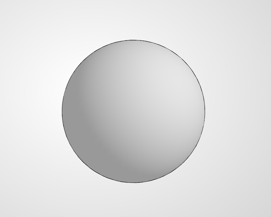
24 mm Precision Steel Ball
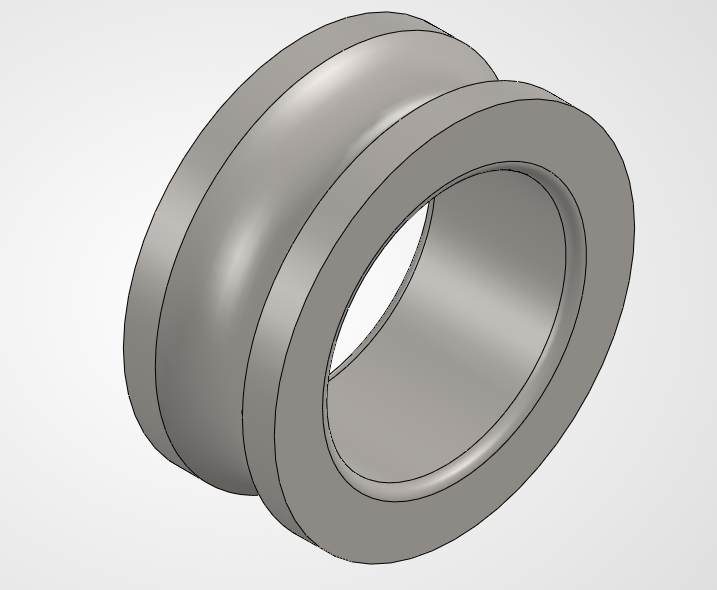
Inner Ring (Bore 25 mm / Raceway Radius 12 mm)
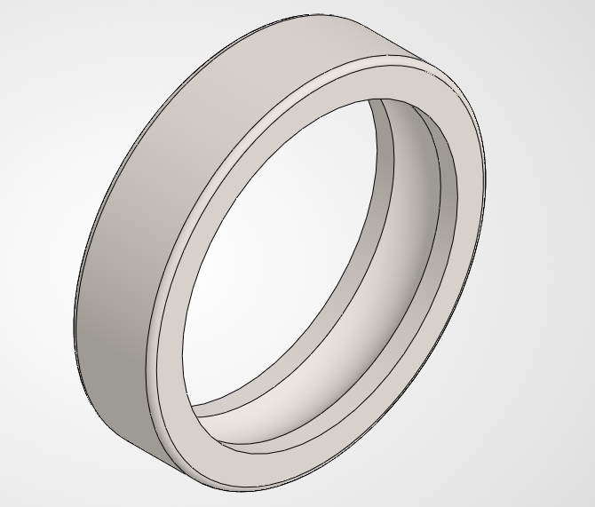
Outer Ring (OD 65 mm / Raceway Radius 12 mm)
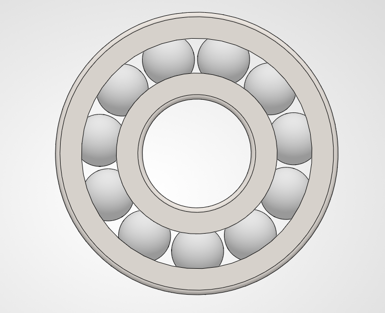
Full Ball Bearing Assembly
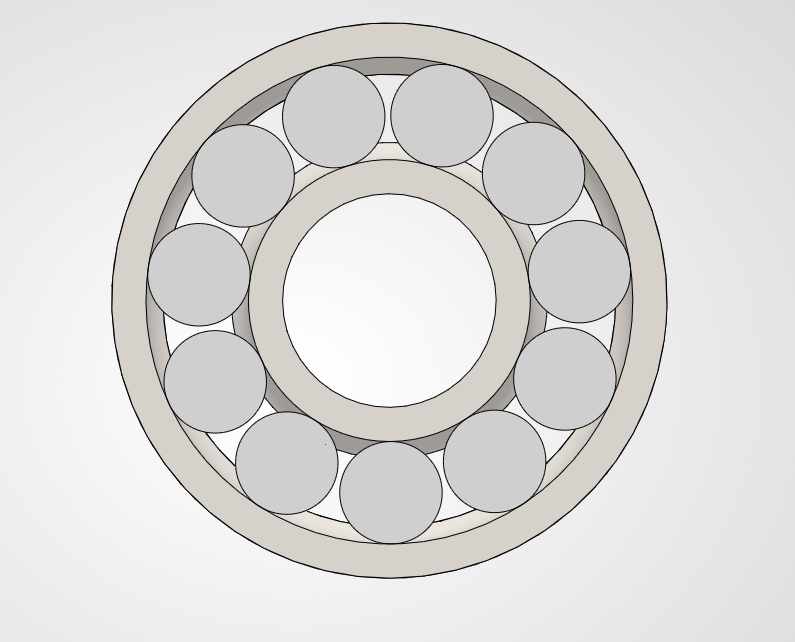
Sectional Cutaway & Raceway Fit View