Parametric Mechanical Cotter Joint
Overview & Industrial Applications
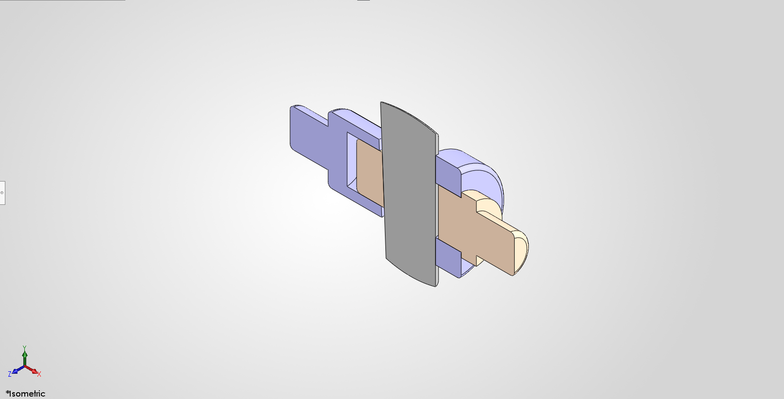
A Cotter Joint is a temporary, rigid mechanical fastener used to connect two coaxial rods subjected to tensile or compressive axial forces along their longitudinal axis. Unlike keyed joints which transmit rotational torque, a cotter joint is designed strictly for linear power transmission and alignment.
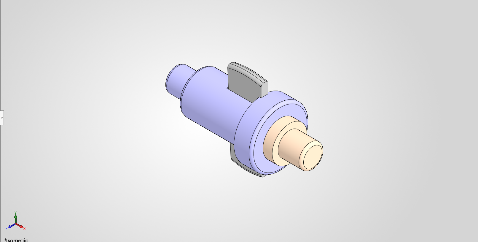
The joint consists of three primary precision-machined elements:
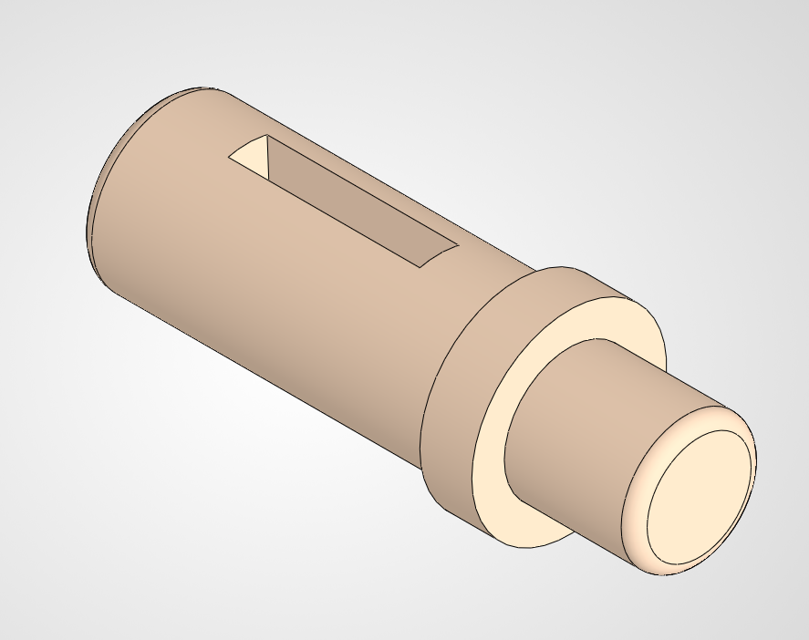
- Spigot End: The male rod end with an enlarged collar and precision-milled slot.
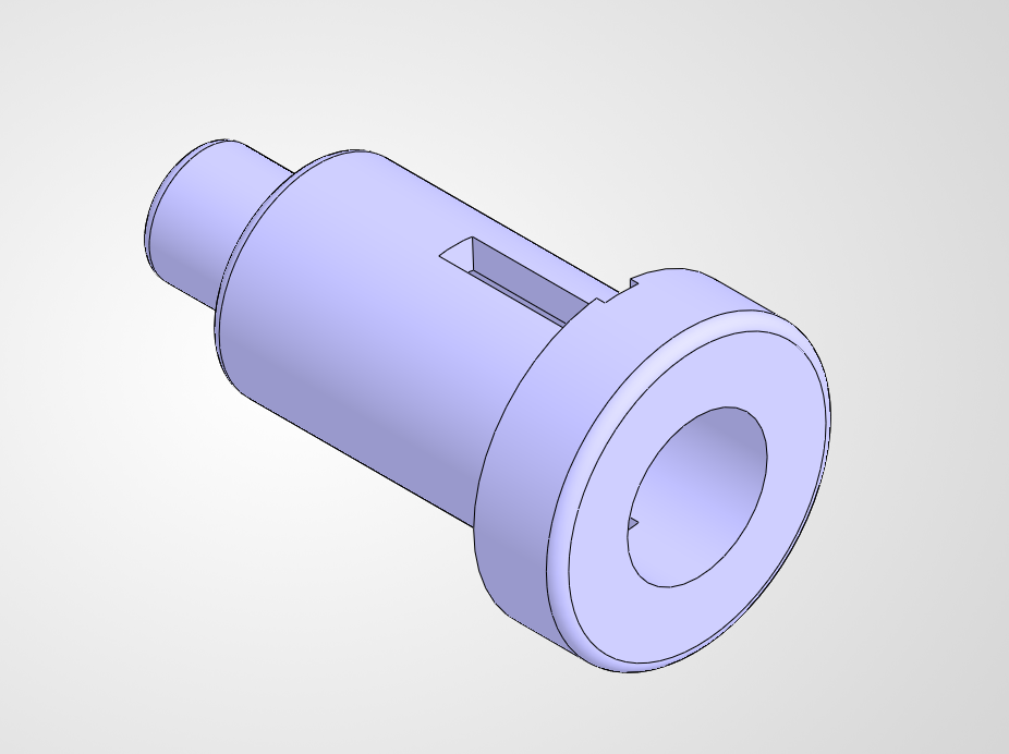
- Socket End: The female housing collar that receives the spigot and features an aligned slot.
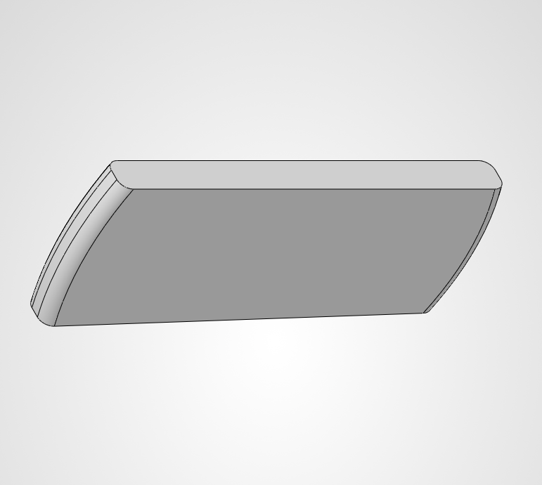
- Cotter Pin: A flat, wedge-shaped steel pin with a 1:24 single-sided taper driven through both slots to lock the assembly in compression.
Common Engineering Applications:
- Connecting piston rods to crossheads in reciprocating engines and pumps.
- Joints between slide valve rods and eccentric rods in steam power machinery.
- Heavy structural tie-rod fasteners in bridge trusses and crane booms.
- Connecting rod ends in hydraulic press actuators and railway tension linkages.
Interactive 3D eDrawing Model
Design Methodology
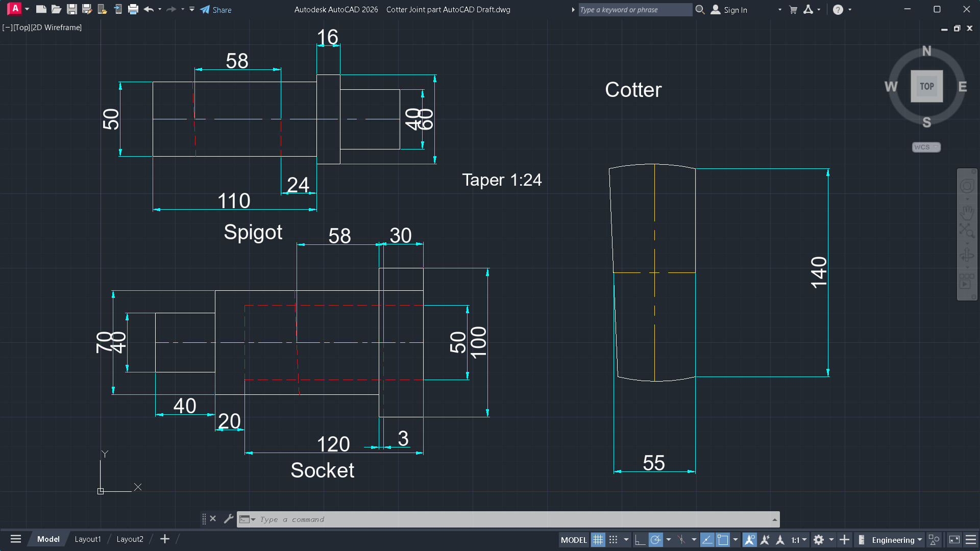
This cotter joint was developed using a Parametric Empirical Design Workflow based on a nominal rod diameter of d = 40 mm.
While classic machine design formulas provide exact theoretical proportions to prevent tensile and shear failure, a purely theoretical model introduces fractional dimensions (e.g., a 48.4 mm shaft diameter). To bridge the gap between theory and real-world manufacturing, I applied standard engineering optimization: rounding key diameters to standard tool sizing (Ø50 mm) and material stock availability (12 mm plate thickness).
Furthermore, I integrated functional clearances (a 3 mm axial draw pocket) to accommodate assembly tolerances and mechanical tightening action, along with stress-relieving fillets (R4) to prevent structural fatigue failure at geometric transitions.
Parametric Dimensioning Matrix
| Feature / Dimension | Formula | Theoretical | Design Value | Engineering Purpose |
|---|---|---|---|---|
| Main Rod Diameter (d) | d | 40 mm | 40 mm | Primary driving variable for the parametric relation tree |
| Spigot Shaft Diameter (d1) | 1.21d | 48.4 mm | 50 mm | Standardized to nominal bar stock for tensile capacity |
| Spigot Collar Diameter (d2) | 1.5d | 60 mm | 60 mm | Provides bearing shoulder against axial compression |
| Socket Outer Diameter (d3) | 1.75d | 70 mm | 70 mm | Outer housing thickness to resist hoop stress |
| Cotter Thickness (t) | 0.3d | 12 mm | 12 mm | Matches standard 12 mm flat plate material stock |
| Cotter Mean Width (b) | 1.375d | 55 mm | 55 mm | Mean width calculated to resist double shear failure |
| Cotter Taper | Taper | 1:24 | 1:24 | Self-locking wedge taper allowing tightening reserve |
| Spigot Collar Thickness (c) | 0.4d | 16 mm | 16 mm | Prevents shearing of the spigot shoulder |
| Spigot Body Length (l) | 2.75d | 110 mm | 110 mm | Total engagement length inside the socket bore |
| Distance (Collar to Hole) | 0.6d | 24 mm | 24 mm | Maintains sufficient material to prevent end tear-out |
| Socket Collar Diameter (d4) | 2.5d | 100 mm | 100 mm | Heavy outer collar resisting expansion under load |
| Socket Collar Thickness | 0.75d | 30 mm | 30 mm | Structural support surrounding the cotter slot |
| Socket Body Length | 3.5d | 140 mm | 140 mm | Full outer sleeve length |
| Total Cotter Length | 3.5d | 140 mm | 140 mm | Full length allowing wedge driving and extraction |
| Fillet Radius (R) | 0.1d | 4 mm | 4 mm | Eliminates sharp corners to reduce stress concentration |
| Axial Draw Clearance | 0.075d | 3 mm | 3 mm | Wedging clearance preventing metal-to-metal seating |
2D Drafting & 3D SolidWorks Models