Heavy-Duty Forged Steel Flanged Coupling
Design Defense & Geometric Rationale
Modeled a high-torque rigid flanged coupling in SolidWorks for a 100 mm power transmission shaft. Rather than utilizing traditional bulky cast iron empirical dimensions, this design is engineered specifically around high-yield forged alloy steel parameters.
Engineering Defense & Load Calculations:
-
1. Material Paradigm — Forged Steel Justification:
A conventional cast iron coupling for a 100 mm shaft requires a massive 200 mm hub diameter and a 50 mm thick flange. This lean design utilizes a 120 mm hub (10 mm wall thickness) and a 22 mm flange. High-strength forged steel (e.g., AISI 1045 or 4340) allows a slim flange thickness rule of thumb of approximately 0.2 × shaft diameter:
0.2 × 100 mm = 20 mm Choosing a 22 mm flange thickness provides a built-in 10% structural safety factor. -
2. Torsional Balance — Mechanical Fuse Protection:
Comparing the shaft torsional strength (Ts) against the double-shear torque capacity of the 6 × M20 bolt pattern (Tb):
• Shaft Torque: Ts = (π / 16) × τs × 100³ ≈ 196,350 τs
• Bolt Pattern Torque: Tb = 6 × [(π / 4) × 20²] × τb × 85 ≈ 160,140 τb
Tb / Ts ≈ 81% The bolts act as an intentional mechanical fuse: under catastrophic overloads, the easily replaceable 20 mm bolts shear at 81% load capacity, protecting the expensive 100 mm drive shaft from yielding. -
3. Ergonomic Tool & Maintenance Clearance:
The bolt circle radius is 85 mm (PCD 170 mm) inside a 220 mm flange, leaving 25 mm radial distance from the hole center to the outer rim. For an M20 hex nut (28 mm across flats), the distance from center to sharpest corner is 16.1 mm. Subtracting 16.1 mm from 25 mm leaves ~9 mm of clearance, providing room for a standard M20 socket wrench without rim interference. -
4. Fastener Stackup & Thread Extension Proportions:
The 75 mm M20 bolt passes through two 22 mm flanges (44 mm grip) and a 12 mm heavy hex nut. Including two 3 mm washers (62 mm stack height), the 75 mm bolt leaves 13 mm protruding past the nut face. This equates to 5 to 6 full exposed thread turns, comfortably exceeding the 2 to 3 thread structural engagement code.
Interactive 2D Engineering Drawing
Interactive 3D eDrawing Model
Parametric Dimensioning Matrix
| Feature / Dimension | Relation / Formula | Design Value | Engineering Purpose |
|---|---|---|---|
| Main Shaft Hole Dia (d) | d | 100 mm | Primary torque transmission shaft bore |
| Flange Outer Diameter (D) | 2.2 × d | 220 mm | Outer perimeter housing bolt circle and wrench clearance |
| Hub Outer Diameter (d_hub) | 1.2 × d | 120 mm | 10 mm forged steel wall around shaft engagement bore |
| Hub Total Engagement Length | 1.42 × d | 142 mm | Full hub depth (120 mm hub sleeve + 22 mm flange) |
| Flange Thickness (tf) | 0.22 × d | 22 mm | Forged steel flange plate thickness with 10% safety margin |
| Bolt Circle Radius (R) | PCD / 2 | 85 mm | 170 mm Pitch Circle Diameter positioning 6 shear bolts |
| Bolt Hole Count & Dia | 6 × d_bolt | 6 × 20 mm | 20 mm clearance holes for high-shear M20 fasteners |
| Transition Fillet Radius | r_fillet | 3 mm | Reduces stress concentration at hub-to-flange junction |
| Bolt Head / Nut Width | Across Flats | 28 mm | Standard M20 heavy hex wrench tooling size |
| Bolt Total Length & Grip | L_bolt | 75 mm | 40 mm smooth unthreaded shank + 35 mm threaded end |
| Nut & Bolt Head Height | 0.6 × d_bolt | 12 mm | Heavy hex nut profile preventing thread stripping |
Technical Drawings & Component Renders
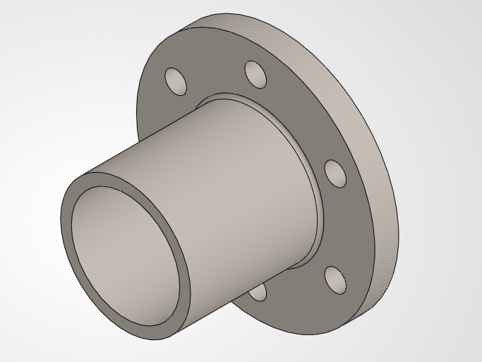
Single Flange Half (OD 220 mm / Bore 100 mm)
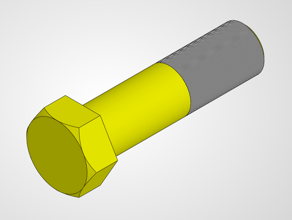
Heavy Hex Bolt (M20 × 75 mm / 40 mm Smooth Shank)
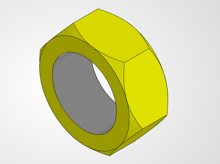
Heavy Hex Nut (28 mm Across Flats / 12 mm Thickness)
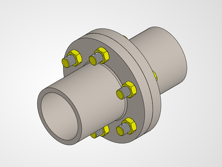
Complete Forged Steel Flanged Coupling Assembly