Custom 3:1 Spur Gear Transmission System
Overview & Design Defense
Modeled a compact, high-precision 3:1 gear reduction drive (18T / 54T, Module 2.5) in SolidWorks. Tooth profiles were generated using fully parametric global equations, tying involute curves, pitch diameters, and root clearances directly to master design variables.
Summary Checklist for Design Review Defense:
- Ratio Optimization: Achieves an exact target speed reduction ratio of 3:1 (54T / 18T).
- Kinematic Reliability: Specifying 18 teeth on the driver pinion strictly avoids interference and profile undercutting without requiring complex negative profile shifts.
- Compact Packaging: Saves 10 mm in center distance (90 mm vs 100 mm) and significantly reduces gearbox enclosure size compared to a conventional 20T/60T configuration.
- Standardized Sourcing: Built upon a standard Module 2.5 involute profile, balancing maximum tooth bending strength with minimal cutter tooling costs.
Interactive 3D eDrawing Model
Parametric Gear Dimensioning Matrix
| Parameter / Dimension | Equation / Relation | Calculated Value | Engineering Significance |
|---|---|---|---|
| Module (m) | m | 2.5 mm | Standard pitch module governing tooth size and strength |
| Pinion Tooth Count (Z1) | Teeth | 18 | Minimum threshold to prevent cutter interference and undercutting |
| Gear Tooth Count (Z2) | 3 * Z1 | 54 | Driven gear tooth count achieving the exact 3:1 speed reduction |
| Pressure Angle (α) | Pressure_Angle | 20° | Standard pressure angle for high load capacity and smooth rolling fit |
| Pinion Pitch Diameter (D1) | m * Z1 | 45 mm | Pitch circle diameter driving speed and velocity calculations |
| Gear Pitch Diameter (D2) | m * Z2 | 135 mm | Pitch circle diameter of driven gear |
| Center Distance (a) | (D1 + D2) / 2 | 90 mm | Saves 10 mm vs 20T/60T, optimizing housing space |
| Addendum (ha) | Module | 2.5 mm | Radial height of tooth above pitch line |
| Dedendum (hf) | 1.25 * Module | 3.125 mm | Radial depth of tooth space below pitch line including bottom clearance |
| Pinion Outside Diameter | Pitch_Dia + (2 * Addendum) | 50 mm | Tip circle diameter (Blank diameter for turning operations) |
| Pinion Root Diameter | Pitch_Dia - (2 * Dedendum) | 38.75 mm | Root circle diameter governing tooth root fillet radius |
| Base Circle Diameter | Pitch_Dia * cos(20°) | 42.28 mm | Base diameter from which the true involute profile originates |
Kinematic Motion & Tooth Mesh Animation
2D Technical Drawings & 3D Renders
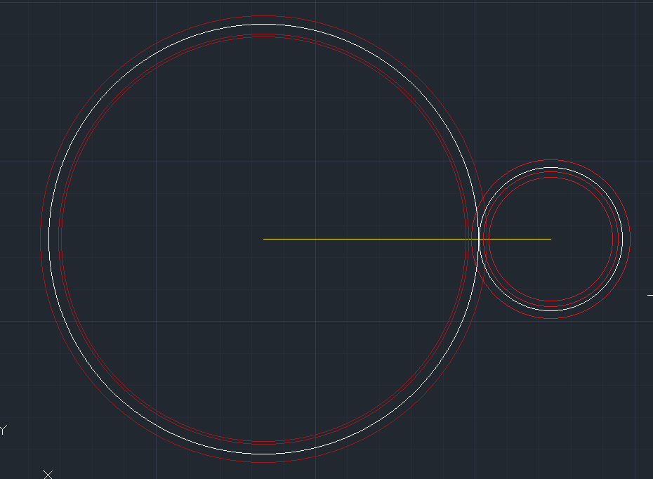
2D AutoCAD Technical Drawing & Tooth Dimensions
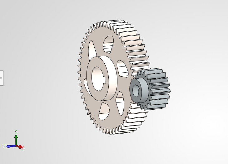
3D Assembly View
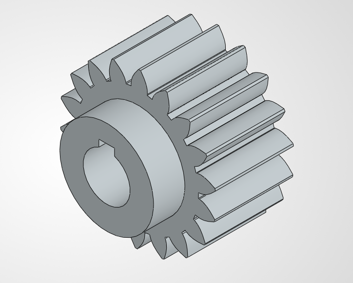
3D 18-Teeth Driver Pinion Component
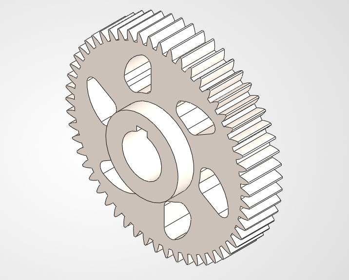
3D 54-Teeth Driven Gear Component